FSCOPE-500K Assembly Instructions
The FSCOPE-500K was previously known as the FSCOPE-250K. Both boards are exactly the same.
The FSCOPE-500K is a 2 channel oscilloscope analog front end for use with the Raspberry Pi Pico or Pico W and the Scoppy Android app.
Assembly
You will need to supply:
- One Raspberry Pi Pico or Pico W
- 7 pairs of 0.1” male headers (or 6 pairs and 2 compatible BNC connectors)
- If the Pico is not to be soldered directly to the board (ie. it will be removable) then 2 sets of 20 0.1” pin headers are also required.
- 3 jumpers (shunts)
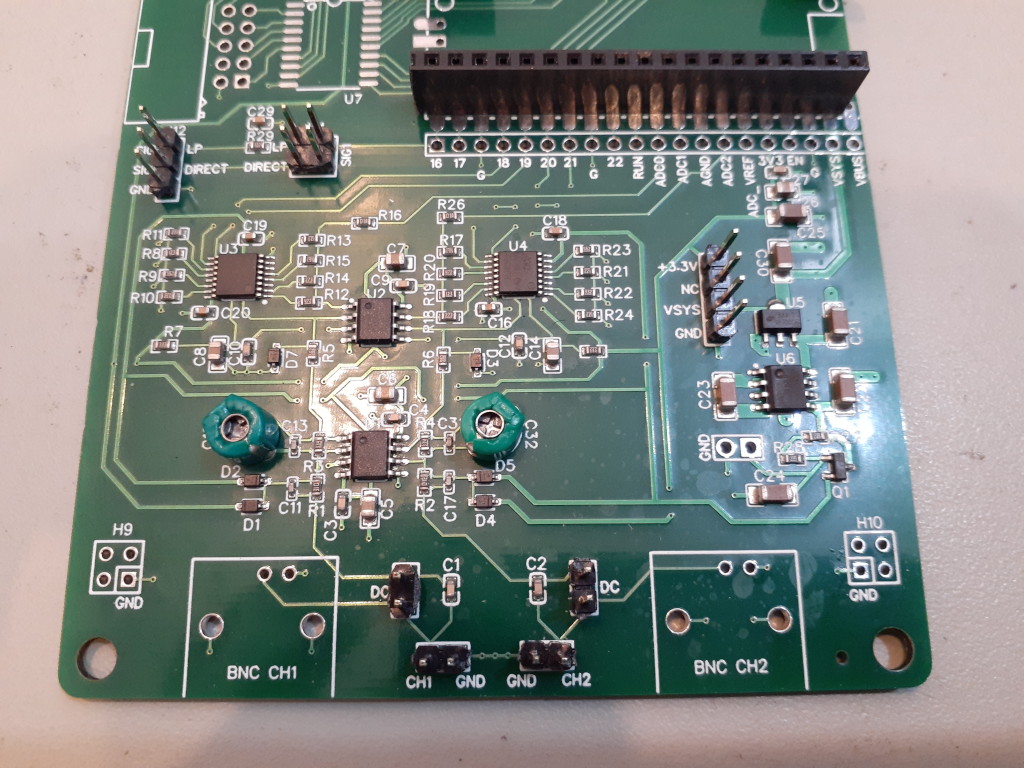
1. Input Connectors (headers)
- Solder pairs of 0.1” male headers to each of CH1/GND and CH2/GND (these can be found at the bottom of the board).
2. AC/DC Coupling pins
- Find the pairs of holes labeled DC. Solder male headers to these and install a jumper (shunt) to connect the two header pins. When the pins are connected like this the channel is in DC coupling mode. Remove the jumper for AC coupling.
3. Signal Generator output and low-pass filter
- Solder headers to the holes labeled ‘SIG’ (or ‘SIG1’) at H12 and optionally to the GND hole.
- Solder headers to the holes at H4.
4. Trimmer Capacitors
- Solder the included green trimmer capacitors to C15 and C32. Polarity is not important.
5. Raspberry PI Pico (or Pico W)
The Pico can be soldered directly to the board or via headers so that it can be easily removed.
6. Input Connectors (BNC connectors - optional)
-
The board can also be used with the inexpensive BNC connectors available from sites such as eBay, Amazon or Aliexpress. The footprint can be found in the datasheet here.
-
If using BNC connectors, solder them to BNC CH1 and BNC CH2.
Firmware Installation
Erase all existing data from the Pico (or Pico W) flash by following the instructions here: Erase Flash
Important. Failure to erase existing data from the flash storage may result in the FSCOPE-500K not working correctly or at all!
Download and install the Scoppy FSCOPE firmware. Instructions are on the Installation & Getting Started page.
The firmware file for the Pico is named scoppy-fscope-500k-pico-vNN.uf2 and the file for the Pico W is named scoppy-fscope-500k-picow-vNN.uf2 (where NN is the version number).
Trimmer capacitor adjustment
If you have Rev. 2 of the FSCOPE board please see FSCOPE-250K-Rev2
If using the signal generator on the FSCOPE/DSO board for the trimmer capacitor adjustment, ensure the jumper on H4 has been removed!!!
Feed a 1kHz square wave into the CH1 input (using jumper wires or 1X probes - do NOT use 10X probes). If the waveform displayed in the app doesn’t look square then adjust the trimmer capacitor (C15) until it does. You’ll need a small screwdriver to do the adjustment. Screwdrivers like those supplied with oscilloscope probes should work.
You can use the Scoppy signal generator to generate the 1kHz square wave as follows:
- If there is a jumper on H4 then remove that.
- Connect the lower SIG pin (DIRECT) on H2 to CH1 with a jumper wire.
- You should see a square wave in the Scoppy app. Ensure the volts/div for CH1 is greater than 600mV (input voltage range 0) otherwise the signal might get clipped.
See the usage instructions for more information about the signal generator pads on the board.
Repeat the procedure for CH2 (the trimmer capacitor for CH2 is labeled C32).
Using the FSCOPE-500K
See Using the FSCOPE-500K and DSO-500K
See Also
Documentation Index
Scoppy on GitHub
Using the App
Scoppy Forum & Support
FHDM Store